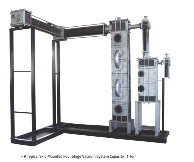

Staging of ejectors becomes necessary for economical operation as the absolute suction pressure decreases. Based upon the use of auxiliary equipment, two and three-stage ejectors can either be condensing or non-condensing types.
Complete skid mounted vacuum system is a combination of Steam Jet Ejector, Condenser and Internal piping all of Graphite.
In Steam Jet Ejector which is based on the ejector-venturi principle, steam issuing through an expanding nozzle has its pressure energy converted to velocity energy. A vacuum is created and the high velocity of steam entrains air or gas and the mixture of gas and steam enters the converging end of the venturi, passes through the diffuser where its velocity energy is converted into pressure sufficient to discharge against a predetermined back pressure.
This combinations is introduced in a Condenser made of Graphite and maximum vapor is condensed and is let out of the condenser unit through outlet connection provided. All the vapors are condensed into its liquid stage and what leaves the system is just Pure Air having vapors in PPM.
Two-Stage Steam Jet Ejectors have the same general field of application as the single stage units.
They handle both condensable and non-condensable gases or vapors, as well as mixtures of the two. The general operating range is between 5" Hg. abs. and 3 mm Hg. abs.
Three-Stage Ejectors are recommended for applications where a two-Stage unit will not provide low enough suction pressure economically.
Applicable range is from 26 mm Hg. abs. to 0.8 mm Hg. abs. Three-Stage Condensing Steam Jet Ejectors consist of a booster ejector, a condenser, and a Two-Stage Ejector consisting of a high-vacuum ejector, inter-condenser, and low vacuum ejector.
In some applications another condenser (after-condenser) can be used at the low vacuum ejector discharge.
This way, through multiple stages vacuum system, All the vapors are condensed into its liquid stage and what leaves the system is just Pure Air having vapors in PPM.
Distillation:
Impervious Graphite is the material which can handle highly corrosive vapors received from the reactors.
| Model | Hold Data on Process Side(mm) | Number of Holdes on Process Side | Hold On DIA Service Side(mm) | Number of Holdes on Process Side | Surface Area on Process side(m)block |
|---|---|---|---|---|---|
| GP1 | 18 | 60 | 9 | 105 | 1 |
| GP2 | 18 | 104 | 9 | 162 | 2 |
| GP3 | 18 | 126 | 9 | 210 | 2.85 |
| GP20 | 22 | 86 | 9 | 120 | 2.07 |
| GP30 | 9 | 301 | 9 | 168 | 3 |
| GP35 | 22 | 125 | 9 | 144 | 3.5 |
| GP45 | 9 | 408 | 9 | 216 | 4.5 |
| GP90 | 9 | 650 | 9 | 368 | 9 |